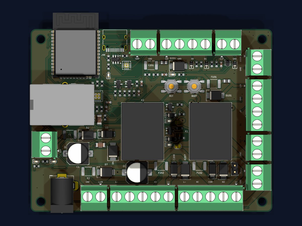
A small board that fits where the old panel was.
One controller design, ordered four ways. It takes the same reader, lock, exit button and door contact wiring the old system used, so the swap is a re-termination, not a rewire.
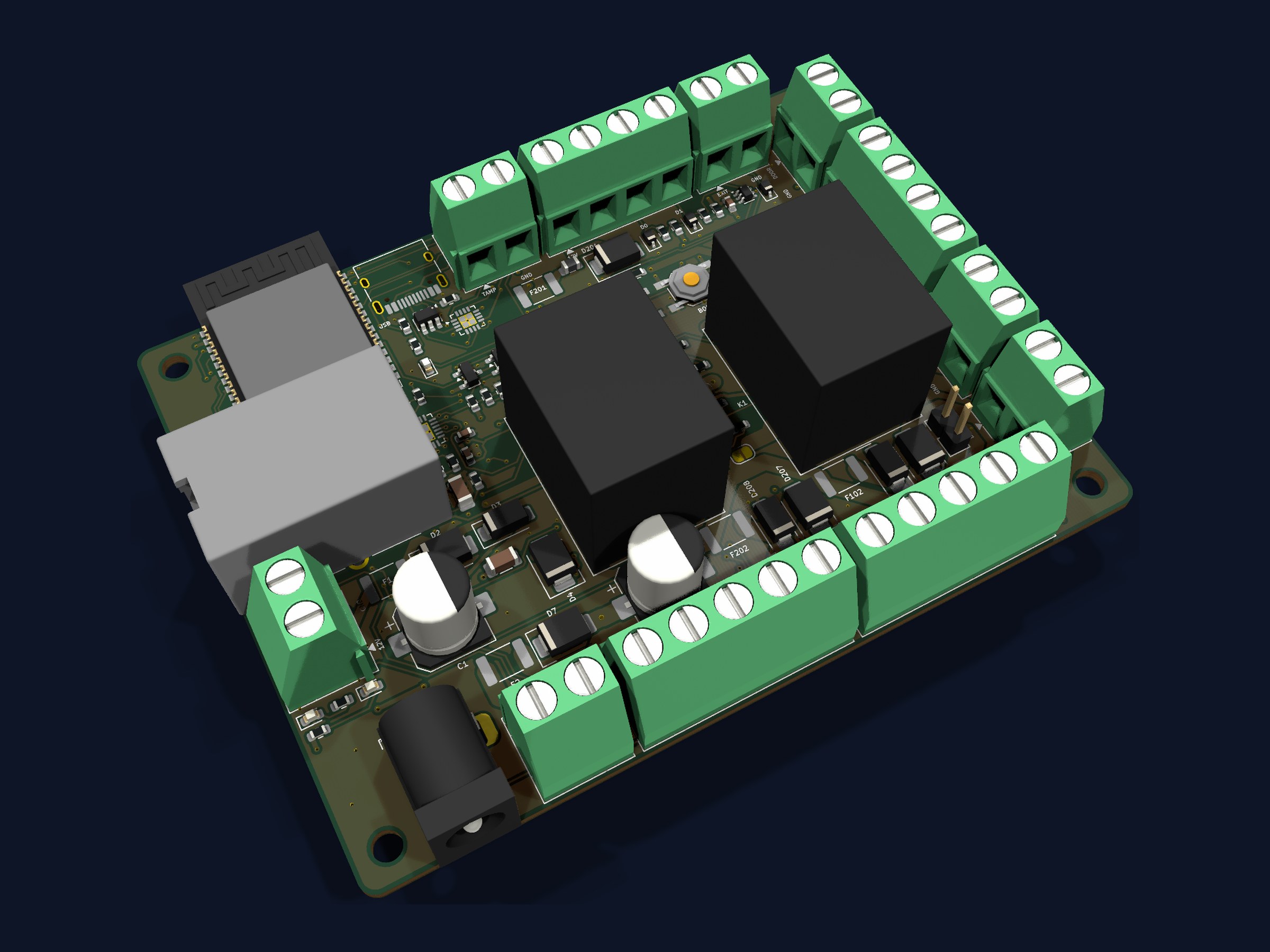
Wireless or wired, one door or two.
Wireless talks to the site network over Wi-Fi. Wired uses a 10/100 Ethernet socket. Single-door and dual-door builds are the same board, with the second channel populated or not.
| Wireless single door |
Wireless dual door |
Wired single door |
Wired dual door |
|
|---|---|---|---|---|
| Board as built | 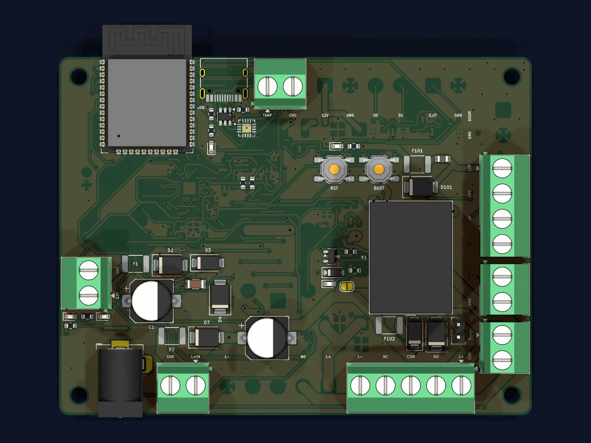 |
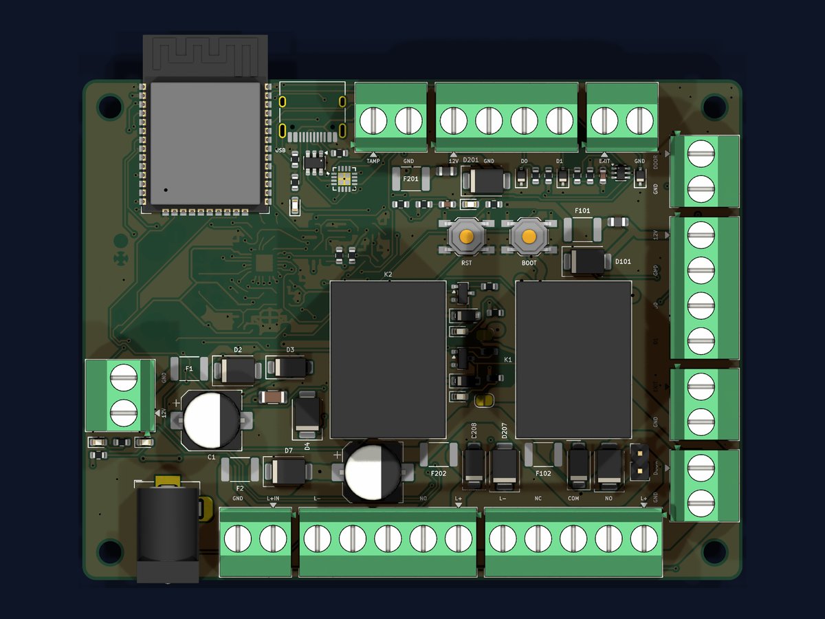 |
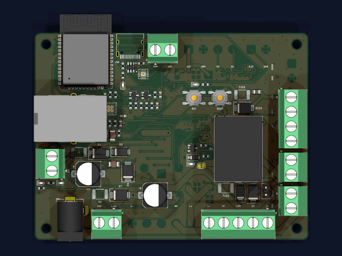 |
 |
| Doors driven | 1 | 2 | 1 | 2 |
| Network | Wi-Fi | Wi-Fi | Ethernet 10/100 | Ethernet 10/100 |
| PoE | - | - | Order option | Order option |
| External antenna (RP-SMA) | Order option | Order option | - | - |
| Reader inputs (12V, GND, D0, D1) | 1 | 2 | 1 | 2 |
| Lock relays, fused 12 V output | 1 | 2 | 1 | 2 |
| Exit button inputs | 1 | 2 | 1 | 2 |
| Door contact inputs | 1 | 2 | 1 | 2 |
| Tamper input | Yes | Yes | Yes | Yes |
| Power in | 12 V DC: screw terminal or 5.5 x 2.1 mm jack, either one | |||
| Separate lock supply input | Yes, so the locks can run off their own battery-backed PSU | |||
| Setup and firmware | USB-C from the browser, then over the air from the panel | |||
| Board | 95 x 72 mm, four corner holes; fits the enclosure the old panel came out of | |||
PoE is an order option on the wired controller only: a splitter is fitted in the enclosure and feeds the controller's 12 V input, so one cable from the switch carries data and power. There is no PoE circuitry on the board itself, which keeps one board covering every order. On a phone, scroll the table sideways to see the wired columns.
Every terminal, labelled.
Screw terminals all the way round the edge, so a door can be wired without the board coming out of the box. The dual-door build populates channel 2; on a single-door build those terminals are simply not fitted.
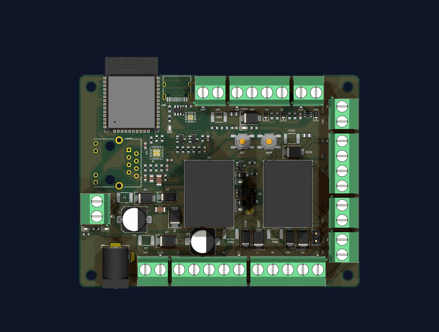
- 1Wireless module and antenna. Wi-Fi to the site network. An external RP-SMA antenna is an order option for metal enclosures and weak-signal spots.
- 2USB-C. Setup and flashing straight from the browser.
- 3Tamper. TAMP, GND. A lid switch raises an alert if the box is opened.
- 4Reader 2. 12V, GND, D0, D1 for the door 2 reader.
- 5Exit 2. EXIT, GND. Push to exit for door 2.
- 6Door contact 2. DOOR, GND. Held-open and forced-door alerts for door 2.
- 7Reader 1. 12V, GND, D0, D1 for the door 1 reader.
- 8Exit 1. EXIT, GND. Push to exit for door 1.
- 9Door contact 1. DOOR, GND for door 1.
- 10Lock 1 out. L-, NC, COM, NO, L+. Fused 12 V and a dry changeover contact, so a maglock or a strike wires to the one terminal.
- 11Lock 2 out. L-, NO, L+ for door 2.
- 12Lock supply in. GND, L+IN. Feed the locks from their own battery-backed PSU, or link it to the controller's 12 V.
- 13Power jack. 5.5 x 2.1 mm, centre positive. This is where a PoE splitter plugs in.
- 1412 V terminal. Screw terminal in parallel with the jack, for wiring straight from a PSU.
- 15Ethernet. 10/100 socket, fitted on the wired controller only (dashed outline).
- 16Reset and boot. Two buttons for recovery; you should never need them in normal use.
- 17Relay per door. One changeover relay per channel, switching the lock supply.
The same five things every door system already has.
Reader, lock, exit button, door contact, power. That is the whole job. Every terminal is labelled on the board, and the panel already knows where each one is wired.
| Existing part | Connects to | Notes |
|---|---|---|
| Wiegand reader | 12V, GND, D0, D1 | 26-bit and 34-bit formats. Proximity, MIFARE, keypad-with-fob and QR readers that output Wiegand all work. One reader per door: Wiegand is point to point, so each reader gets its own pair of data lines. |
| Electric strike or maglock | L+, COM, NO / NC, L- | The relay switches the lock supply through a dry changeover contact. Use NO for fail-secure strikes, NC for fail-safe maglocks. Pulse length is set per door in the panel. |
| Exit button (request to exit) | EXIT, GND | Normally-open push button or a no-touch sensor. Pressing it pulses the relay and logs an exit. |
| Door contact | DOOR, GND | Magnetic reed or microswitch. Enables held-open and forced-door alerts. |
| Power | 12V, GND or the barrel jack | Reuse the existing 12V PSU and its battery backup. On the wired controller a PoE splitter can feed the jack instead. |
| Lock power | L+IN, GND | A separate input, so heavy maglocks run off their own battery-backed access PSU and leave the controller and readers on a clean supply. |
| Lid switch | TAMP, GND | Optional tamper input. Opening the enclosure raises an alert in the panel. |
| Second door (dual-door build) | channel 2 terminals | Its own reader, relay, exit button and door contact, mapped to its own door in the panel. |
Fail-safe or fail-secure is chosen per door in the panel. Fail-safe (maglock) releases on power loss so people can always get out; fail-secure (strike) stays locked and relies on the mechanical handle for egress. Match the setting to the lock and to your fire strategy, and keep the existing break-glass or fire-alarm release in the lock supply where one is fitted.
Existing fobs keep working. The controller reads the Wiegand code straight off the reader and matches it to a person in the panel. Nobody needs a new fob or card; import the codes you have, or capture them with enrolment mode.
Set up a controller from a web page. No installer software.
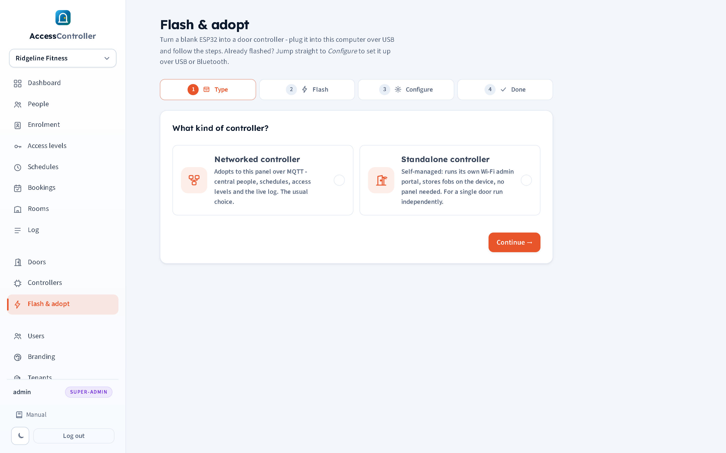
- Plug a new controller into a laptop with a USB-C cable.
- Open the panel's flash and adopt wizard: pick the type, flash it, configure it.
- Give it the Wi-Fi or network details and the panel address.
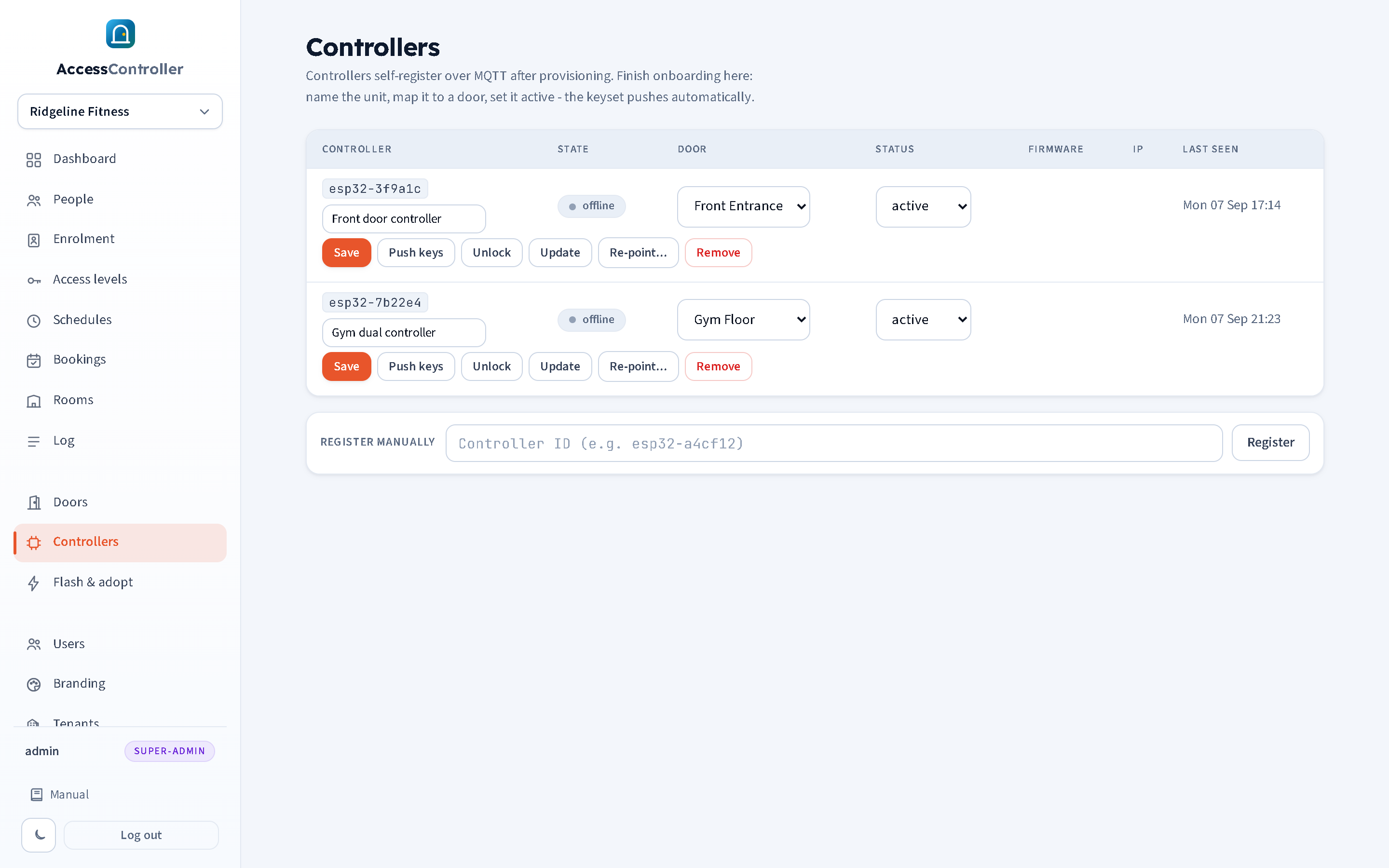
- It appears in the controller pool, ready to be assigned to a tenant and a door.
- Later firmware updates go out over the air from the panel, and controllers can be re-pointed to a different panel remotely.
Works offline
The access list lives on the controller. If the internet link drops, fobs keep opening doors and schedules keep applying. Events are held and sent to the panel when the link returns.
Held-open, forced-door and tamper alerts
With a door contact fitted, the panel logs doors propped open past the pulse time and doors opened without a valid unlock. A lid switch on the tamper input reports the box being opened.
Remote unlock
A remote unlock button per controller in the panel, for letting someone in from wherever you are. Every remote unlock is logged against your user.
Not sure what you have on the wall?
Send us a photo of the old panel and a reader and we will tell you what the swap looks like.