Chapter 05
Controllers and hardware
This chapter is for the installer. It covers the supported controller boards, what connects to them, the default wiring for each board type, flashing and adopting a new controller from the browser, onboarding it into a tenant, over-the-air updates, moving a controller to a new server, and reading controller health.
Supported boards
The controller firmware runs on three families of board. The same firmware image is used for every unit of a family; nothing is compiled per site.
| Board | Network | Notes |
|---|---|---|
| Classic ESP32 devkit (WROOM-32 / WROVER) | Wi-Fi | The general-purpose choice. Cheap, widely available. |
| Olimex ESP32-POE-ISO | Wired Ethernet with PoE | One cable for power and data, isolated. Ignores Wi-Fi settings and uses DHCP. Recommended where a network point is available. |
| ESP32-S3 (for example ESP32-S3-N16R8) | Wi-Fi | A different chip family from the classic ESP32 with its own firmware build. The flash wizard picks the right build automatically. |
There are two firmware kinds:
- Networked controller (the usual choice): adopts to the panel over MQTT, gets its keyset from the panel, reports events. Everything in this manual assumes networked controllers.
- Standalone controller: no panel at all. It runs its own protected Wi-Fi admin page where fobs are enrolled with the reader, named and deleted. Useful for a single door run independently. It is flashed from the same wizard but is otherwise outside this manual.
What connects to a controller
Per door (per channel on a dual-door unit):
- Wiegand reader: any 26-bit or 34-bit Wiegand reader. Data 0 (usually the green wire) and Data 1 (usually white) go to the controller; the reader's 0 V is common with the controller's; the reader takes its power from the lock/reader supply (typically 12 V), not from the controller. The controller enables internal pull-ups on D0 and D1, so external pull-up resistors are usually unnecessary. Frames other than 26 or 34 bits are ignored and noted on the serial console.
- Lock relay: one output pin drives a relay module. The relay contact switches the lock's own supply. See the fail-safe warning in chapter 3.
- Exit button (REX): a normally-open push button between the REX pin and 0 V. Pressing it always releases the door (free egress) and is logged as an exit-button event. Set the pin to
-1if there is no button. - Door position sensor: a reed switch or door contact between the door pin and 0 V, closed when the door is closed. Enables door forced and door held open alerts (chapters 3 and 4) and the door opened / door closed lines in the Log. Set the pin to
-1if there is no sensor. - Real-time clock (optional): a DS3231 module on the SDA/SCL pins keeps accurate time through power cuts without network. Without it the controller gets time from the network (SNTP) after boot.
- Power: 5 V USB or the board's own regulator input; PoE on the Olimex board. Keep controller power separate from lock power.
A dual-door controller is one board with two of everything above, wired to the channel 1 and channel 2 pins.
Default GPIO wiring
The firmware ships with per-chip defaults so that a freshly flashed board works before anything is configured. The defaults are chosen to be free on both a generic devkit and the Olimex POE board (whose Ethernet PHY uses GPIO 12, 17, 18, 19, 21, 22, 23, 25, 26 and 27). Every pin can be changed in Settings (chapter 13); the values are sent to the controller when it is provisioned.
Classic ESP32 and Olimex ESP32-POE-ISO, channel 1
| Signal | GPIO | Notes |
|---|---|---|
| Wiegand D0 | 32 | reader green wire |
| Wiegand D1 | 33 | reader white wire |
| Lock relay | 4 | active high by default (energise = HIGH); switchable to active low |
| Exit button (REX) | 14 | to 0 V, internal pull-up; -1 if absent |
| Door position sensor | 15 | reed to 0 V, closed = low, internal pull-up; -1 if absent |
| RTC SDA / SCL | 13 / 16 | optional DS3231 |
| Setup button | 0 (BOOT) | hold low at power-up to force setup mode |
Classic ESP32 dual-door, channel 2 (panel defaults)
The Settings page pre-fills channel 2 with these values. They must not clash with channel 1. On an Olimex POE board GPIO 25, 26 and 27 are used by the Ethernet PHY, so choose other free pins for channel 2 there.
| Signal | GPIO |
|---|---|
| Wiegand D0 | 25 |
| Wiegand D1 | 26 |
| Lock relay | 27 |
| Exit button (REX) | 13 |
| Door position sensor | 2 |
ESP32-S3, channel 1
The S3 has reserved pins that must be avoided: 26 to 32 (SPI flash), 33 to 37 (OPI PSRAM on -R8 parts; touching these hangs the chip), 19 and 20 (USB), 43 and 44 (UART0), and 0, 45 and 46 (strapping). The firmware defaults for the S3 all sit in the always-safe 1 to 18 range.
| Signal | GPIO | Notes |
|---|---|---|
| Wiegand D0 | 4 | |
| Wiegand D1 | 5 | |
| Lock relay | 6 | active high by default |
| Exit button (REX) | 7 | to 0 V, internal pull-up |
| Door position sensor | 15 | reed to 0 V, closed = low |
| RTC SDA / SCL | 8 / 9 | optional DS3231 |
| Setup button | 0 (BOOT) | hold at power-up for setup mode |
Note: the pin values held in the panel's Settings page are what actually get written to a controller when it is provisioned. The Settings defaults are the classic ESP32 values (D0 32, D1 33, relay 4, REX 14, door 15). If you are provisioning an ESP32-S3 from the panel, change the channel 1 pin map in Settings to the S3-safe values above before sending settings, otherwise the S3 will be told to use GPIO 33 and may hang.
Other fixed behaviour: the relay pulse defaults to 4000 ms, the held-open alert to 60 s until the door's own Alert if held open value arrives in its keyset (chapter 3), the door contact is debounced over 200 ms, and a stalled controller reboots itself after 30 s (hardware watchdog).
Flash and adopt: step by step
The Flash & adopt page turns a blank board into a door controller entirely from the browser. No installer software is needed. You need a laptop with Chrome or Edge, a USB cable to the board, and the panel open on a secure page.
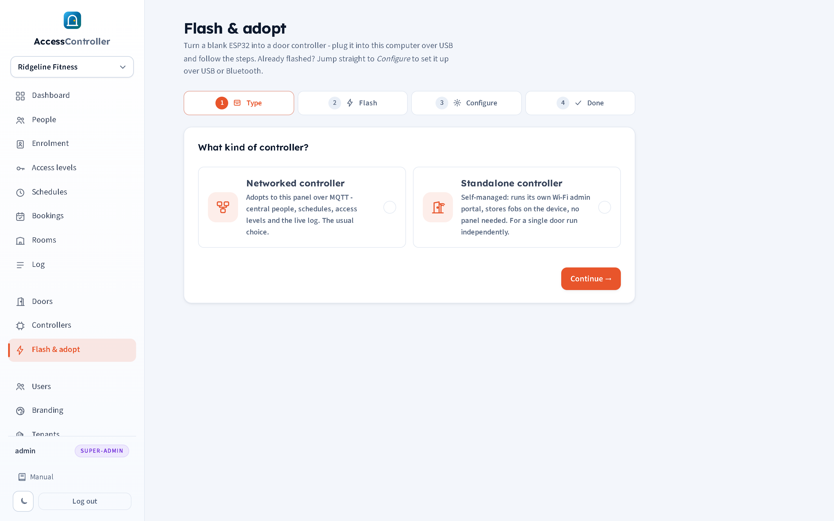
The four steps across the top are Type, Flash, Configure and Done. They are also buttons: click any of them to jump straight there. That matters most for a board that is already flashed, where you want to go directly to Configure and send it its settings over USB or Bluetooth without flashing it again. Jumping ahead without choosing a firmware type first assumes Networked controller, which is what you want in all but a handful of cases.
Note: Web Serial and Web Bluetooth only work on a secure page. Use the panel's
https://address (hosted panels are already HTTPS; a self-hosted panel also listens on port 8443 with a self-signed certificate, so accept the browser warning once), or openhttp://localhost:8080/flashon the panel machine itself. Safari on iPhone and iPad supports neither Web Serial nor Web Bluetooth.
Before you start
- On Settings (chapter 13) enter the controller Wi-Fi network and password (not needed for the Olimex wired board), the controller type (single or dual door), the pin maps if they differ from the defaults, and check the Adoption address and MQTT port the controllers will connect to. These are what the wizard sends to the board.
- Plug the board into the laptop over USB. Most boards need no driver on current Windows, macOS or Linux; if the port does not appear, install the USB-serial driver for the board's chip (typically CP210x or CH340).
Step 1: Type
Choose Networked controller (adopts to this panel) or Standalone controller. Press Continue.
Step 2: Flash
The page shows, for the chosen kind, which chip builds are staged on the panel ("ready", a partial count, or "not built"). Press the install button, pick the serial port in the browser's chooser, and let it run. The right build for the connected chip is selected automatically (classic ESP32 and ESP32-S3 have different bootloader offsets; this is handled for you). A first install takes about a minute.
If the board will not connect: hold BOOT, tap RST (reset), release BOOT, then retry. Some boards need this every time to enter download mode.
Upload firmware binaries lets an administrator stage new builds on the panel for a chip (four .bin files per chip: bootloader, partitions, boot_app0 and firmware). Most users never need this; 2plus1 stages builds on hosted panels.
As soon as flashing finishes, the wizard automatically reopens the USB port and sends the settings from step 3 to the board. Watch the log box under the flash button. If it reports that the port could not be reopened, go to step 3 and press the send button yourself.
Step 3: Configure
This step sends the Wi-Fi, the adoption address and port, the MQTT credentials and the pin map to the controller, which saves them, reboots and registers with the panel. First choose Doors on this controller: single door or dual door (two readers and relays). Then choose how to reach the board:
USB cable (default). A summary shows the Wi-Fi, adoption address and pins that will be sent, with a Change in Settings link. Press Send settings to device, pick the port again if asked, and wait for ACSCFG OK in the log. The board restarts and should appear under Controllers within a minute. Query device reads the board's current settings back (passwords masked) without changing anything; use it to check what a board believes.
If the board does not answer, press its RESET button and click send again. The board listens for settings over USB at any time, including in normal operation, so this also works later to re-provision a unit on the bench.
Bluetooth. No cable needed after flashing. Put the controller into setup mode by holding BOOT while powering it on. Press Scan & connect and pick the controller from the chooser: it advertises as ACS-Cfg- followed by the last six characters of its ID. Once connected, the Wi-Fi and address fields are pre-filled from Settings and can be overridden here; Read current shows what the board holds, Write settings to controller sends the new values and the board reboots onto Wi-Fi. Bluetooth configuration is only available while the controller is in setup mode; it is switched off during normal running.
Web Bluetooth works in Chrome and Edge on desktop and Android. It does not work in Safari or on iOS.
Step 4: Done
For a networked controller, go to Controllers to finish onboarding. For a standalone controller, connect a phone to the board's own Wi-Fi network (ACS-Door- followed by its ID, default password access1234 unless you changed it in step 3) and its admin page opens automatically.
The setup portal fallback
A controller with no saved settings, or one powered up with BOOT held, starts its own Wi-Fi access point named ACS-Setup- followed by its ID with a captive setup page at http://192.168.4.1. The page takes the Wi-Fi network and password, the panel address and MQTT port, and optional MQTT username and password, then saves and restarts. Use this when there is no laptop to hand. The same setup mode is also where Bluetooth configuration is available.
Adopting a controller into a tenant
After provisioning, the controller connects to the panel and announces itself. The panel registers it automatically and logs a Controller registered system event. Finish onboarding on the Controllers page:
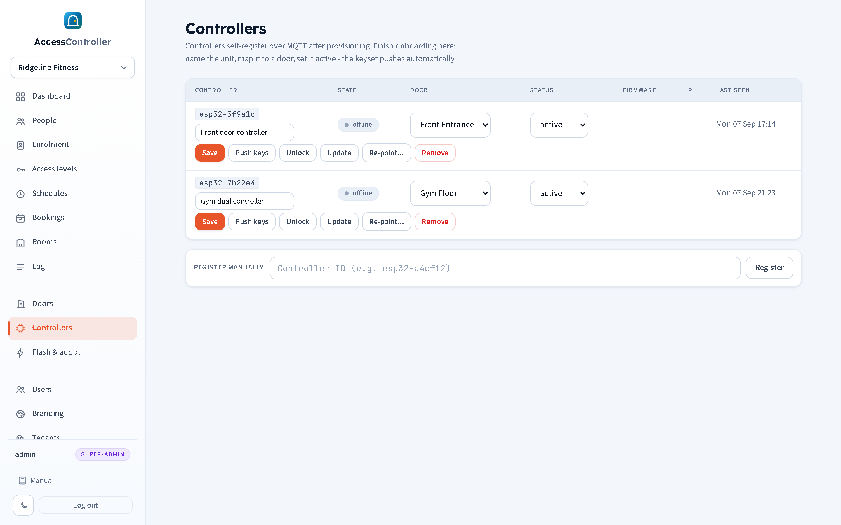
- Give it a friendly name ("Front door controller").
- Choose its Door (this maps channel 1; for the second door of a dual controller use the door's own detail page and pick channel 2, as in chapter 3). A controller set to dual door is listed there with "- dual" after its ID, so you can see which units have a second channel to assign.
- Set Status to active.
- Press Save. The panel compiles the keyset for that door and pushes it; the message "Controller saved - keyset pushed" confirms it.
Status values: pending (registered, not yet onboarded; it receives no keyset), active (in service), disabled (kept in the list but ignored; no keyset is pushed and its events are not attributed to a door).
Which tenant does a new controller land in?
- If the controller's ID was registered manually first (the Register manually box at the bottom of the Controllers page, using the ID printed on the board's serial console or on its setup network name, for example
esp32-a4cf12), it is created in the tenant you are switched into and simply comes online when it connects. This is the recommended path for a provider commissioning a customer's door: switch into the customer, register the ID, then flash and adopt. - If an unknown controller connects first, it is placed in the unassigned pool (owned by no tenant) so that no customer can see another customer's hardware. A super admin then assigns it to a tenant. The current release's Controllers page does not yet show a pool section, so use manual registration in the right tenant before the controller first connects.
A controller only ever receives the fobs of the tenant that owns it.
Controller status and health
Each row on the Controllers page shows:
- State: online if the controller has reported within the last 10 minutes, otherwise offline. Controllers send a status heartbeat about once a minute and re-announce themselves on every reconnect.
- Firmware version and chip family (
esp32oresp32s3). - IP address on the site network and Last seen time.
The dashboard tile "Controllers online" shows the same information as a count. A controller that shows offline is still opening its door from its saved keyset; what it cannot do is receive new fobs or send events until it reconnects. Chapter 17 has the offline checklist.
Action buttons
- Push keys: recompile and re-send the door's keyset now. Use it after fixing a mapping or if you suspect the controller has an old list. The panel also pushes automatically on every relevant change and on a periodic timer.
- Unlock: fire the relay once (same pulse as a granted scan). Logged as Remote unlock with no person.
- Update: send the latest staged firmware for this controller's chip to it over the air. See below.
- Re-point...: move the controller to a different panel. See below.
- Remove: delete the controller from the panel. It will re-register in the pool if it connects again.
Over-the-air (OTA) updates
Update tells the controller to download the firmware image staged on the panel for its chip and flash it into its spare firmware slot, then reboot into it. The download rides HTTP on the panel's own port, or HTTPS through the reverse proxy if Public HTTPS URL is set in Settings (chapter 13). An ota_start event is logged when the download begins; a failure raises an ota_failed alert with the reason.
Things to know:
- The controller must be online.
- The firmware has two slots but no automatic roll-back. An image that does not boot leaves the unit in a boot loop until it is re-flashed over USB. Test an update on one unit before pushing it to a site.
- Units flashed with very old firmware (before the two-slot layout) must be flashed once over USB before OTA works.
Re-pointing a controller to a new server
Re-point... opens a small form on the controller's row: new server address, MQTT port (1883 by default), and optional MQTT user and password. Send it and the controller saves the new address, reboots and connects to the new panel, where it registers as a new controller. No site visit or USB cable is needed.
- The controller must be online with the current panel to receive the command.
- Leave the user and password blank to carry over this panel's MQTT credentials. If the new server uses different credentials, type them here. Sending blank credentials to a server that requires different ones leaves the controller unable to connect, and it cannot then be re-pointed remotely (chapter 17 explains the recovery).
- The controller's firmware must support re-pointing; if the Re-point button has no effect, update the firmware over the air first, then re-point.
Hardware installation checklist
- Mount the controller in the same enclosure the old panel came out of, or a small IP-rated box, within cable reach of the reader, lock and exit button.
- Wire the reader (D0, D1, 0 V, 12 V from the reader supply), relay (to the lock supply, NO or NC to suit fail-safe or fail-secure), exit button and door contact per the GPIO table for the board.
- Fit a flyback diode across a maglock coil. Put the lock supply on a battery-backed PSU. Keep a break-glass or fire-alarm interface in the lock circuit where required.
- Power the controller (USB 5 V or PoE) and confirm the reader's LED and the serial banner (115200 baud) if you have a console.
- Flash and adopt from the panel, or use the setup portal.
- On the Controllers page: name, door, active, Save.
- Present a known fob: the log should show OK and the relay should click. Press the exit button: the log should show Exit button. Open and close the door: the log should show Door opened then Door closed (if a sensor is fitted). Open the door without a grant: the log should show Door forced.
- Note the controller ID on the door's paperwork.